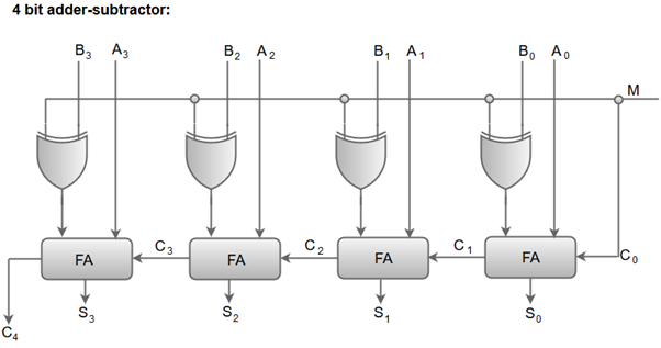
Binary Adder-SubtractorThe Subtraction micro-operation can be done easily by taking the 2's compliment of addend bits and adding it to the augend bits. Note: The 2's compliment can be obtained by taking the 1's compliment and adding one to the least significant pair of bits. The 1's compliment can be implemented with inverters, and one can be added to the sum through the input carry.The Arithmetic micro-operations like addition and subtraction can be combined into one common circuit by including an exclusive-OR gate with each full adder. The block diagram for a 4-bit adder-subtractor circuit can be represented as: 
Next TopicBinary Incrementer |