DSBC (Double Sideband with Carrier) transmissionIn DSB C transmission, the carrier signal is transmitted along with the message signal. Here, the carrier generation at the receiving end is not required because the carrier is already present. It is a major advantage of the DSBC over the suppress carrier transmission. But, it has low efficiency as compared to the DSBSC transmission. Here, we will discuss the DSBC modulator, DSBC demodulator, and efficiency. Let the message signal be m(t) and the carrier signal be ACcosωCt. The modulation of the two can be represented as: V(t) = AC [1 + m(t)] cosωCt The resultant waveforms of the carrier signal, message signal, and the modulation of these two signals is shown below: 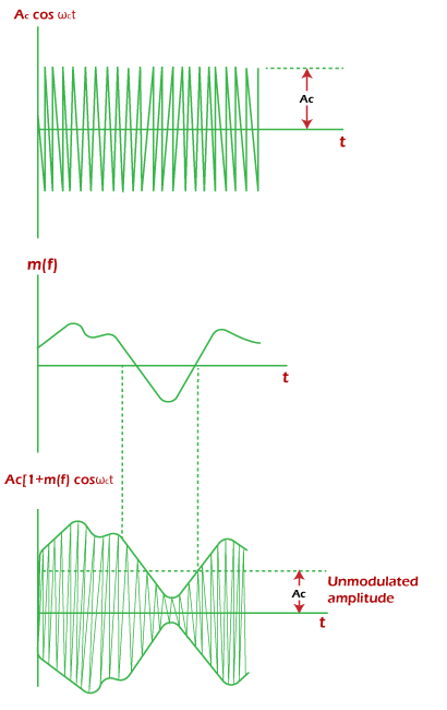 DSB C ModulatorThe multiplier generates the two sidebands by multiplying the carrier and message signals. Here, the only message signal is filtered out at the receiver. If a carrier is added by the summer in the DSBSC generator, we get a DSB-C transmission. The diagram of the DSBC modulator is shown below:  The pulse train of the signal can be represented as: S(t) = 1/2 + 2/π (cosωCt - 1/3 cos3ωCt + 1/5 cos5ωCt - 1/7 cos7ωCt ...) It consists of a diode, an adder, and a bandpass filter. The diode is considered ideal, and the carrier signal is high frequency. The diode conducts when the carrier and message signal is positive. It is regulated by the stronger signal, i.e., the carrier signal. When the diode is switched ON, the combined output appears across its output, which is given by: Y(t) = (m(t) + AcosωCt) s(t) Y(t) = (m(t) + AcosωCt) [1/2 + 2/π (cosωCt - 1/3 cos3ωCt + 1/5 cos5ωCt - 1/7 cos7ωCt ...)] The above output is applied to the bandpass filter. It passes the signal '2/π m(t)cosωCt' and the carrier component 'A/2 cosωCt.' It clearly depicts that the output is the Double Sideband with Carrier Amplitude Modulation. DSB C DemodulatorThe signal is recovered at the receiver. The process of demodulation is to recover the baseband signal from the modulated signal. Envelope detectorThe recovery circuit is shown below: 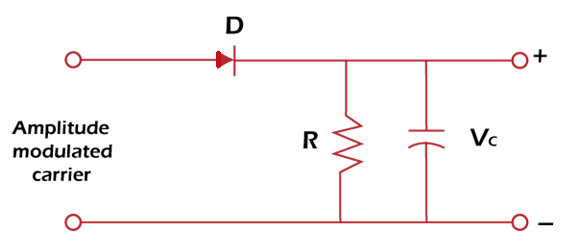 It consists of a diode and an RC circuit. The RC circuit is a parallel combination of resistor and capacitor. The capacitor first charges to the voltage equal to the positive voltage of the carrier. The resistor is essential in the circuit because it helps the capacitor to discharge. Without the resistor, the capacitor cannot follow the carrier when it changes its peak. The diode again conducts when the amplitude of the input carrier increases. The graph representing the capacitor voltage cycle is shown below: 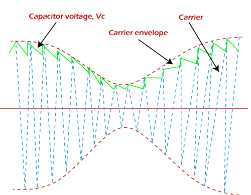 The above graph follows the shape of an envelope with the sawtooth wave. A small distortion can occur, which can be easily removed by using appropriate filters. SpectrumLet's consider the three sinusoidal signals for the spectrum. The three sinusoidal components are A1m1cosω1t, A2m2cosω2t, and A3m3cosω3t. It represents the one side spectrum, as shown below: 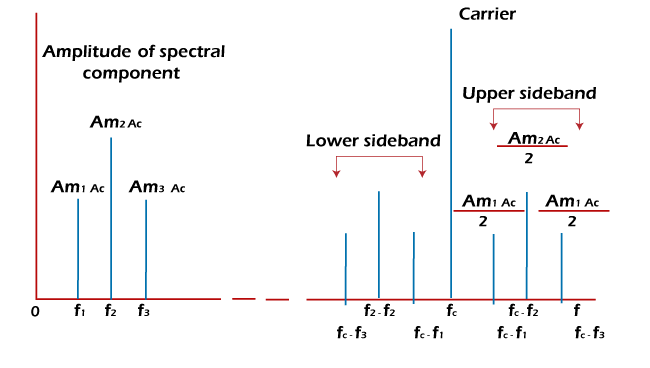 The modulated spectrum will appear on both sides because of the DSB transmission, which is shown below: 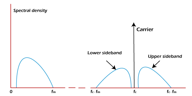 The upper sideband's spectral lines are at the sum frequencies Fc + F1, Fc + F2, and Fc + F3. The lower sideband's spectral lines are at the difference frequencies Fc - F1, Fc - F2, and Fc - F3. EfficiencyThe efficiency of Amplitude Modulation is defined as the ratio of sideband power to the total power. Efficiency = Ps/Pt The total power is the sum of sideband power and the carrier power. Pt = Ps + Pc Thus, we can also define the efficiency as: Efficiency = Ps/ Ps + Pc Efficiency = Am2/(2 + Am2) Where, Am is the modulation index of the signal The maximum power efficiency can be achieved if the modulation index is 1. If, Am = 1 Efficiency = Am2/(2 + Am2) Efficiency = 1/3 x 100 Efficiency = 33.33% It is the efficiency of the DSB with carrier. Next TopicSSBSC |