| |

Armature Reaction in DC MachineWhat is a DC machine?Electrical energy may be converted into mechanical energy or the other way around using an electromechanical device known as a DC machine. The DC machine, sometimes referred to as the DC motor or DC generator, converts electrical energy into mechanical energy and mechanical energy into electrical energy, respectively. The same device can function as a generator or a motor. Both the DC generator and the DC motor have the same architecture. Working of DC machineThe basis for the operation of a DC machine is the torque produced when a current-carrying conductor coil is placed in a magnetic field. This torque causes the conductor coil to rotate inside the magnetic field. To determine the direction of this created torque, use the Fleming's left-hand rule. Following is the computed generated force. Where, F = Magnitude of the generated force
Armature Reaction in DC MachineThe carbon brushes are always positioned at the magnetic neutral axis in a DC machine. The geometric neutral axis and the electromagnetic neutral axis meet in a no-load state. Therefore, when the machine is loaded, its armature flux has a triangle wave structure and is directed along the interpolar axis (the axis between the magnetic poles). The main field becomes cross-magnetized as a result, and the brush axis becomes the direction of the armature current flow. Due to the cross-magnetization effect, flux is concentrated at the leading pole tip while a motor is operating and on the trailing pole tip when a generator is operating. The term "armature reaction" refers to how the armature flux affects the main flux. A DC motor's resultant flux is stronger at the tips of the leading pole and weaker at the tips of the following pole. 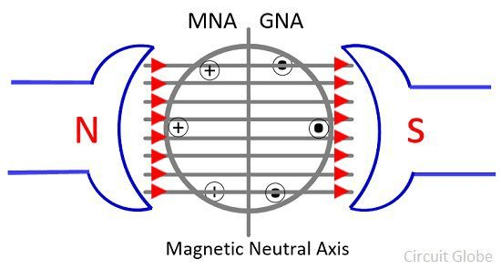
What do Leading and Trailing Pole Tips mean?The leading tip of the pole is the tip in which the armature conductors enter influence, and the trailing tip is the opposing tip in the opposite direction. For instance, if the motor turns counterclockwise in the image above, the lower tip for the North Pole would be the leading tip, and the higher tip for the South Pole would be the leading tip. The tips are switched if indeed the motion is reversed (like with a generator). The magnetic neutral axis changes under load along the direction of rotation in a DC generator and in the opposite direction in a DC motor as a result of cross magnetization. If the brushes are left in their original placements, the generator's or motor's produced e.m.f. will decrease, causing significant sparking during commutation. This is because only the brushes coils are subject to commutation, and the alternate pole affects the commuting coil (changes its location from the north to south pole or vice versa). As a result, the direction of the current quickly switches from +i to -i or vice versa. As a result, the coil encounters a very high reactance voltage (L* di/dt), which destroys the brushes and commutator section by escaping as heat energy and sparking. The following techniques are employed to lessen the aforementioned negative impacts and enhance the functioning of the machine: Brush ShiftThe brushes might be moved in a way that reduce the air gap between the flux, such as all along direction of rotation for generator action and opposite the direction of rotation for motor action. This will raise the speed of the motor and lower the induced voltage in the generator. The demagnetizing magneto motive force (mmf) resulting from this is provided by: F=NI Where, N - numbers of turns of the inductive coil I - current Brush shift is severely constrained; therefore, the brushes must be moved to a new location if the load, the rotation's direction, or the mode of operation changes. Due to this, only extremely tiny machines may use brush shift. The brushes are likewise fixed in this location at a position that corresponds to the regular load and mode of operation. These drawbacks make this strategy less popular in general. Inter PoleAlmost all medium and big sized DC machines now utilize inter poles due to the brush shift's limitations. The inter polar axis has long, thin poles called inter poles. In the case of generator action, the succeeding pole is the one that will be rotated next, while in the case of motor action, the following pole is the one that will be rotated after the generator action. The inter pole's purpose is to balance the inter polar axis's armature response mmf. Since inter poles and the armature are connected in series, the direction of the inter pole changes when the armature's current flows in a different direction. This is as a result of the armature reaction's mmf direction being in the interpolar axis. The reactance voltage (L di/dt) is totally neutralized by the commutation voltage, which is also provided for the coil that is undergoing commutation. As a result, sparking is prevented. Inter polar windings carry the armature current and operate as intended regardless of load, rotational direction, or mode of operation because they are always kept in series with the armature. To guarantee that they exclusively affect the coil that is undergoing commutation and that their impact does not extend to the other coils, inter poles are made smaller. To prevent saturation and enhance responsiveness, the base of the interpoles is made broader. Compensating WindingThe commutation difficulty with DC devices is not the sole issue. When operating with significant loads, the cross-magnetizing armature response may result in extremely high flux densities at the leading pole tip and trailing pole tip of the generator and motor, respectively. This coil may produce an induced voltage high enough to cause a flashover between the related neighboring commutator segments because it is situated close to the commutation zone (at the brushes), where the air temperature may already be high as a result of the commutation process. This flashover might affect nearby commutator segments and eventually ignite a full-scale fire that spreads from brush to brush over the commutator surface. The voltage L* di/dt that appears across the adjacent commutator segments of the machine may also increase to a value high enough to result in flash over between the adjacent commutator segments when the machine is subjected to rapidly changing loads. As the coil underneath it has the greatest inductance, this would begin at the pole's core. This might result in a fire similar to the one previously mentioned. This issue is more severe when the load is shifting from generating to motor action, as the induced e.m.f. and voltage L di/dt will then support one another. The compensating winding is made up of parallel-to-the-shaft conductors implanted in the pole face that carry an armature current in the opposite direction as the armature conductors beneath that pole arc. The primary field has been fully compensated. Inductor in the armature circuit is also reduced, which enhances system responsiveness. No matter the load, rotational direction, or mode of operation, compensating winding performs adequately. Naturally, it aids in commutation since the inter polar winding is relieved of its responsibility to offset the armature mmf beneath the pole arc. Major problems of compensating windings:
Points to Remember
Next TopicWhat is an AC Servo Motor
|
 For Videos Join Our Youtube Channel: Join Now
Feedback
- Send your Feedback to [email protected]
Help Others, Please Share


