UML Collaboration Diagram
The collaboration diagram is used to show the relationship between the objects in a system. Both the sequence and the collaboration diagrams represent the same information but differently. Instead of showing the flow of messages, it depicts the architecture of the object residing in the system as it is based on object-oriented programming. An object consists of several features. Multiple objects present in the system are connected to each other. The collaboration diagram, which is also known as a communication diagram, is used to portray the object's architecture in the system.
Notations of a Collaboration Diagram
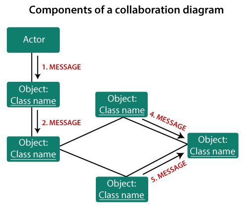
Following are the components of a component diagram that are enlisted below:
- Objects: The representation of an object is done by an object symbol with its name and class underlined, separated by a colon.
In the collaboration diagram, objects are utilized in the following ways:
- The object is represented by specifying their name and class.
- It is not mandatory for every class to appear.
- A class may constitute more than one object.
- In the collaboration diagram, firstly, the object is created, and then its class is specified.
- To differentiate one object from another object, it is necessary to name them.
- Actors: In the collaboration diagram, the actor plays the main role as it invokes the interaction. Each actor has its respective role and name. In this, one actor initiates the use case.
- Links: The link is an instance of association, which associates the objects and actors. It portrays a relationship between the objects through which the messages are sent. It is represented by a solid line. The link helps an object to connect with or navigate to another object, such that the message flows are attached to links.
- Messages: It is a communication between objects which carries information and includes a sequence number, so that the activity may take place. It is represented by a labeled arrow, which is placed near a link. The messages are sent from the sender to the receiver, and the direction must be navigable in that particular direction. The receiver must understand the message.
When to use a Collaboration Diagram?
The collaborations are used when it is essential to depict the relationship between the object. Both the sequence and collaboration diagrams represent the same information, but the way of portraying it quite different. The collaboration diagrams are best suited for analyzing use cases.
Following are some of the use cases enlisted below for which the collaboration diagram is implemented:
- To model collaboration among the objects or roles that carry the functionalities of use cases and operations.
- To model the mechanism inside the architectural design of the system.
- To capture the interactions that represent the flow of messages between the objects and the roles inside the collaboration.
- To model different scenarios within the use case or operation, involving a collaboration of several objects and interactions.
- To support the identification of objects participating in the use case.
- In the collaboration diagram, each message constitutes a sequence number, such that the top-level message is marked as one and so on. The messages sent during the same call are denoted with the same decimal prefix, but with different suffixes of 1, 2, etc. as per their occurrence.
Steps for creating a Collaboration Diagram
- Determine the behavior for which the realization and implementation are specified.
- Discover the structural elements that are class roles, objects, and subsystems for performing the functionality of collaboration.
- Choose the context of an interaction: system, subsystem, use case, and operation.
- Think through alternative situations that may be involved.
- Implementation of a collaboration diagram at an instance level, if needed.
- A specification level diagram may be made in the instance level sequence diagram for summarizing alternative situations.
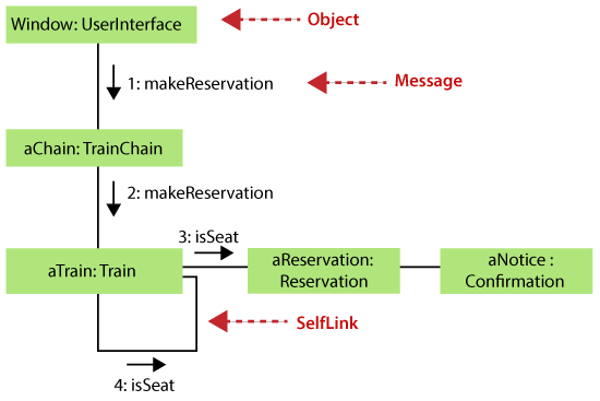
Example of a Collaboration Diagram
Benefits of a Collaboration Diagram
- The collaboration diagram is also known as Communication Diagram.
- It mainly puts emphasis on the structural aspect of an interaction diagram, i.e., how lifelines are connected.
- The syntax of a collaboration diagram is similar to the sequence diagram; just the difference is that the lifeline does not consist of tails.
- The messages transmitted over sequencing is represented by numbering each individual message.
- The collaboration diagram is semantically weak in comparison to the sequence diagram.
- The special case of a collaboration diagram is the object diagram.
- It focuses on the elements and not the message flow, like sequence diagrams.
- Since the collaboration diagrams are not that expensive, the sequence diagram can be directly converted to the collaboration diagram.
- There may be a chance of losing some amount of information while implementing a collaboration diagram with respect to the sequence diagram.
The drawback of a Collaboration Diagram
- Multiple objects residing in the system can make a complex collaboration diagram, as it becomes quite hard to explore the objects.
- It is a time-consuming diagram.
- After the program terminates, the object is destroyed.
- As the object state changes momentarily, it becomes difficult to keep an eye on every single that has occurred inside the object of a system.
|

 For Videos Join Our Youtube Channel: Join Now


